2. Instrument Overview
To reduce data from FLAMINGOS-2 effectively, and to understand its limitations, it is helpful to know the basics of the design and operating modes. These instruments are very well documented on the Gemini Observatory website (see F2) and in the literature (see [EE3]). This chapter contains a very brief summary of the instrument; links to more in-depth material appear throughout the discussion.
2.1. Optical Path
The optical path, illustrated in the schematic diagram below, shows relative positions of the MOS and dekker wheels, as well as wheels holding filters and grisms. The selection of aperture slit-mask, filter, and grism defines the observing configuration for each exposure.
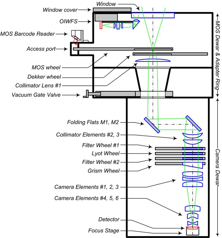
FLAMINGOS-2 optical path. Light from the telescope focal plane enters from the top, and passes through a slit-mask or dekker. A filter and a grism may also be inserted into the beam, depending on the observing configuration, before light enters the camera and illuminates the detector (bottom). Click to enlarge.
2.2. Focal Plane
The FLAMINGOS-2 field of view (FoV) is circular with a diameter of 6.1 arcmin, which underfills the detector in imaging mode (see the Figure below). In spectroscopic MOS mode the field is truncated by the dekker to about 2 arcmin in the detector x- direction.
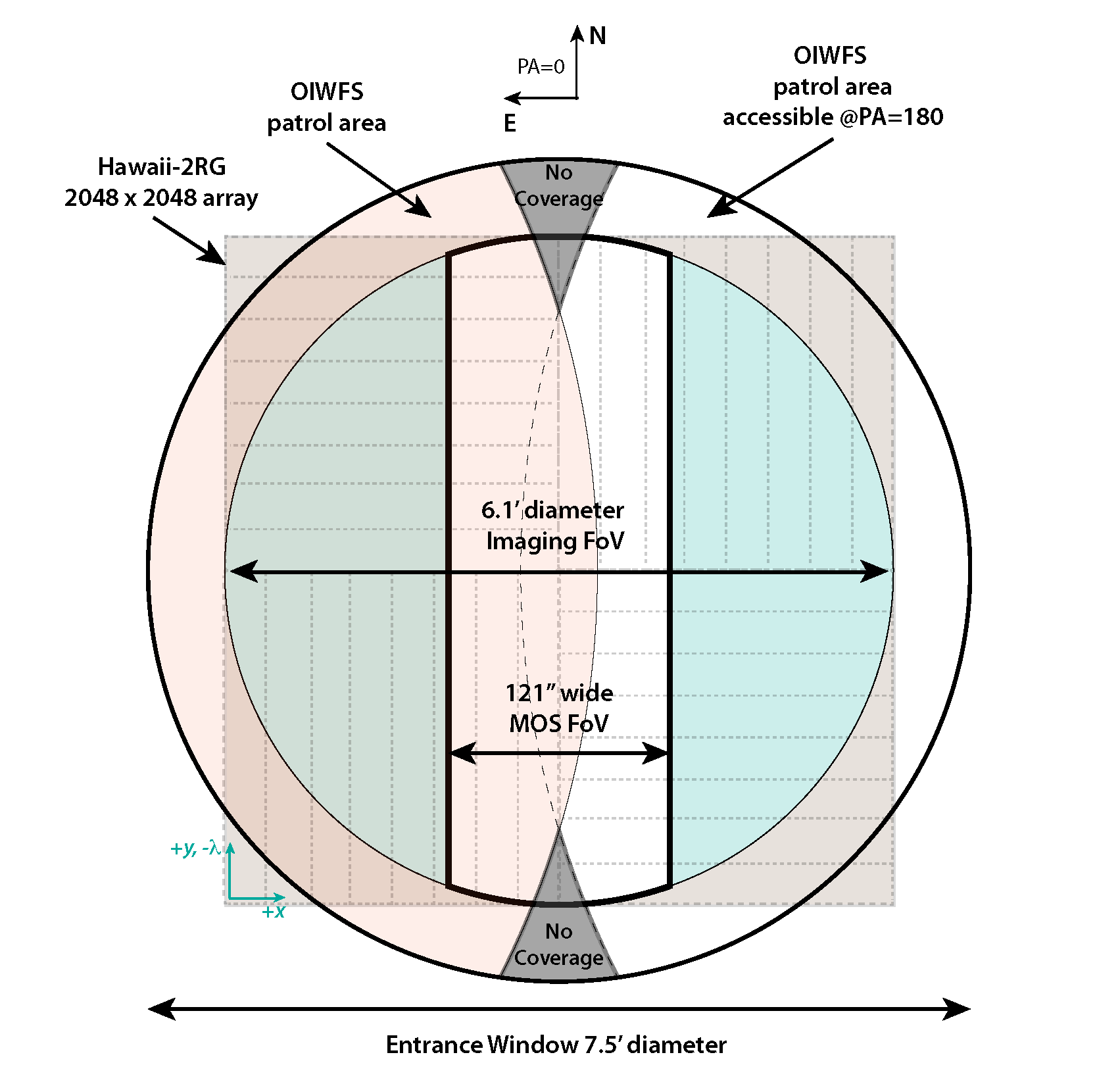
The 6.1 arcmin circular Imaging FoV (light blue) and the 2 arcmin wide MOS (white) FoV lie within the spectrograph entrance window (dark black circle). The detector (light brown) is divided into 32 regions (light dashed grey rectangles) for parallel readout, with the raw image origin indicated at lower left (teal arrows). In imaging mode the corners of the detector are unilluminated. The extent of the OIWFS patrol area (light orange) is indicated for PA \(=0^{\circ}\) though a mirror-symmetric area is accessible at PA \(=180^{\circ}\). Two small areas inaccessible to the OIWFS are indicated (dark grey). Click to enlarge.
2.2.1. Detector
FLAMINGOS-2 uses a single Hawaii-2RG HgCdTe detector array, with the following characteristics:
| Image format | \(2048 \times\ 2048\) array; \(18\mu m\) pixels |
| Output channels | 32 |
| Spatial scale | 0.1787 arcsec/pixel at f/16 |
| Spectral response | \(0.9 - 2.4\mu m\) |
| Dark Current | 0.5 \(e^- \mathrm{s}^{-1} \mathrm{pix}^{-1}\) |
| Read Noise | \(11.7 e^-\) (single CDS read) |
| \(<5 e^-\) (8 CDS read) | |
| Gain | \(4.44 e^- \mathrm{ADU}^{-1}\) |
| Well depth | \(155400e^-\) ; 35000 ADU |
The array response is linear to <0.5% from about 4000 - 22,000 ADU. See the F2 instrument pages for details.
The detector read-out may be optimized for the target source brightness: bright-, medium-, or faint-object mode. They differ in the number of correlated double-sample (CDS) reads of the array: 1, 4, and 8 respectively. All reads for an exposure are performed onboard the detector electronics, and only the final averaged pixel values are written to the raw image. The number of CDS reads affects the read-out time and the resulting read noise. At very high count rates the exposure duration per sample should be sufficiently short so that:
- the count rate remains in a regime where any non-linearity can be corrected
- minimal signal is lost during the time it takes to read the array
These conditions might be violated locally for, e.g., bright field stars.
2.3. Configurations
The FLAMINGOS-2 imaging spectrograph can be configured in the following ways:
- Imaging of a circular 6.1 arcmin FoV
- Long-slit spectroscopy with moderate resolution and a variety of slit widths
- Simultaneous multi-object spectroscopy of targets within a \(6.1 \times 2.0\) arcmin portion of the imaging FoV, with custom fabricated slitlets
2.3.1. Imaging
A set of facility filters may be used to obtain IR images in a few passbands of the 6.1 arcmin circular FoV. Acquisition images are also obtained for all spectroscopic targets, but their short duration may limit their scientific utility. The facility filters are: Y, J, H, Ks, K-blue, K-red. Additional band-limiting filters, Jlow, JH, HK, and K-long are also available for spectroscopic modes.
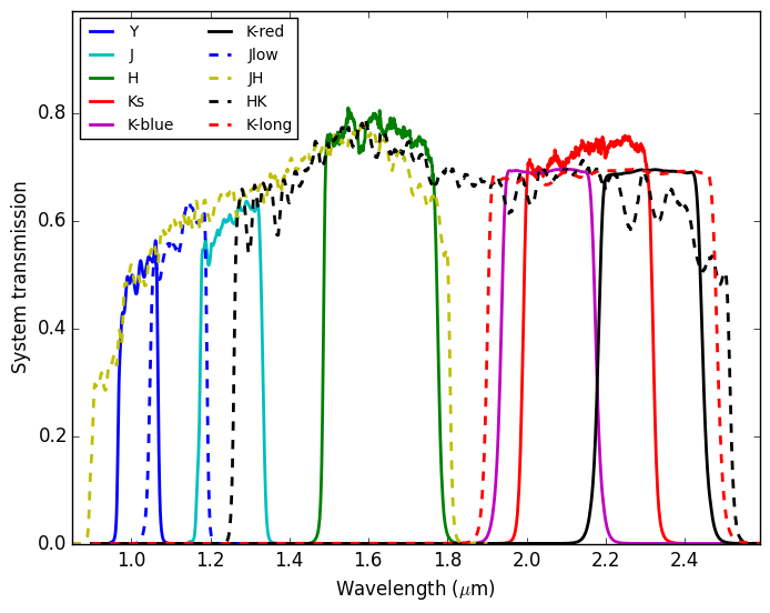
Total system transmission of the facility filters (for K-blue, K-red, and K-long only the scaled filter transmission is plotted). Transmission of the band-limiting filters is shown with dashed curves. Quantitative filter descriptions are available on the Gemini F2 web pages.
2.3.2. Spectroscopy
Long-slit or multi-object spectroscopy requires obtaining an acquisition exposure with a the slit mask inserted, but without the disperser to ensure that light from all targets in the field passes through the intended slitlets. These acq exposures are not useful for data reduction. The grisms place the spectra from the slit(s) onto the detector format for subsequent exposures.
2.3.2.1. Aperture Masks
The F2 facility longslit masks each have a length of 263 arcsec, and have widths as shown in the table below. The spectral resolution degrades for widths larger than 2 pixels.
| Width (pix) | 1 | 2 | 3 | 4 | 6 | 8 |
| Width (arcsec) | 0.18 | 0.36 | 0.54 | 0.72 | 1.08 | 1.44 |
There are also 9 slots available for MOS spectroscopy with custom masks. A schematic of the locations of the aperture masks (and the open position) in the MOS wheel is shown below.
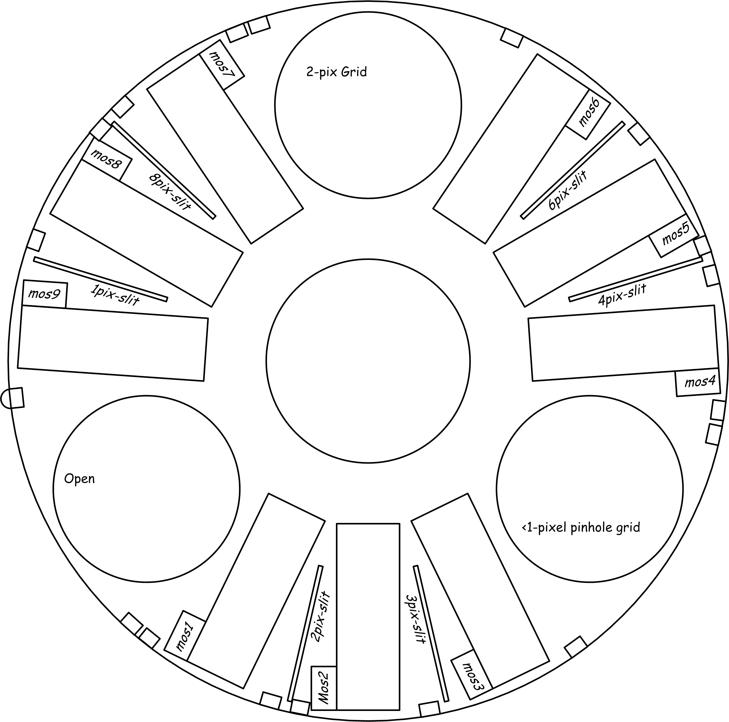
Location of aperture masks in the F2 MOS wheel. Click to enlarge.
Blah.
2.3.2.2. Dispersers
Three grisms are available as dispersive elements in the spectroscopic configurations. Together with passband limiting filters, the grisms provide low- and intermediate-spectral resolution over nearly the full range of the detector sensitivity. See the table below for their attributes, and the F2 website for more quantitative detail.
| Grism | Filter | Order | Wavelength (\(\mu m\)) | Dispersion (A) | Resolution |
|---|---|---|---|---|---|
| JH | JH | 1 | 1.25 | 6.677 | 900 |
| HK | HK | 1 | 1.65 | 7.826 | 900 |
| R3K | Jlow | 6 | 1.10 | 1.667 | 2700 |
| J | 5 | 1.25 | 2.022 | 2800 | |
| H | 4 | 1.65 | 2.609 | 2800 | |
| Ks | 3 | 2.20 | 3.462 | 2900 | |
| K-long | 3 | 2.19 | 3.495 | 2900 |
The total system throughput of the commonly used grism + filter combinations is shown below.
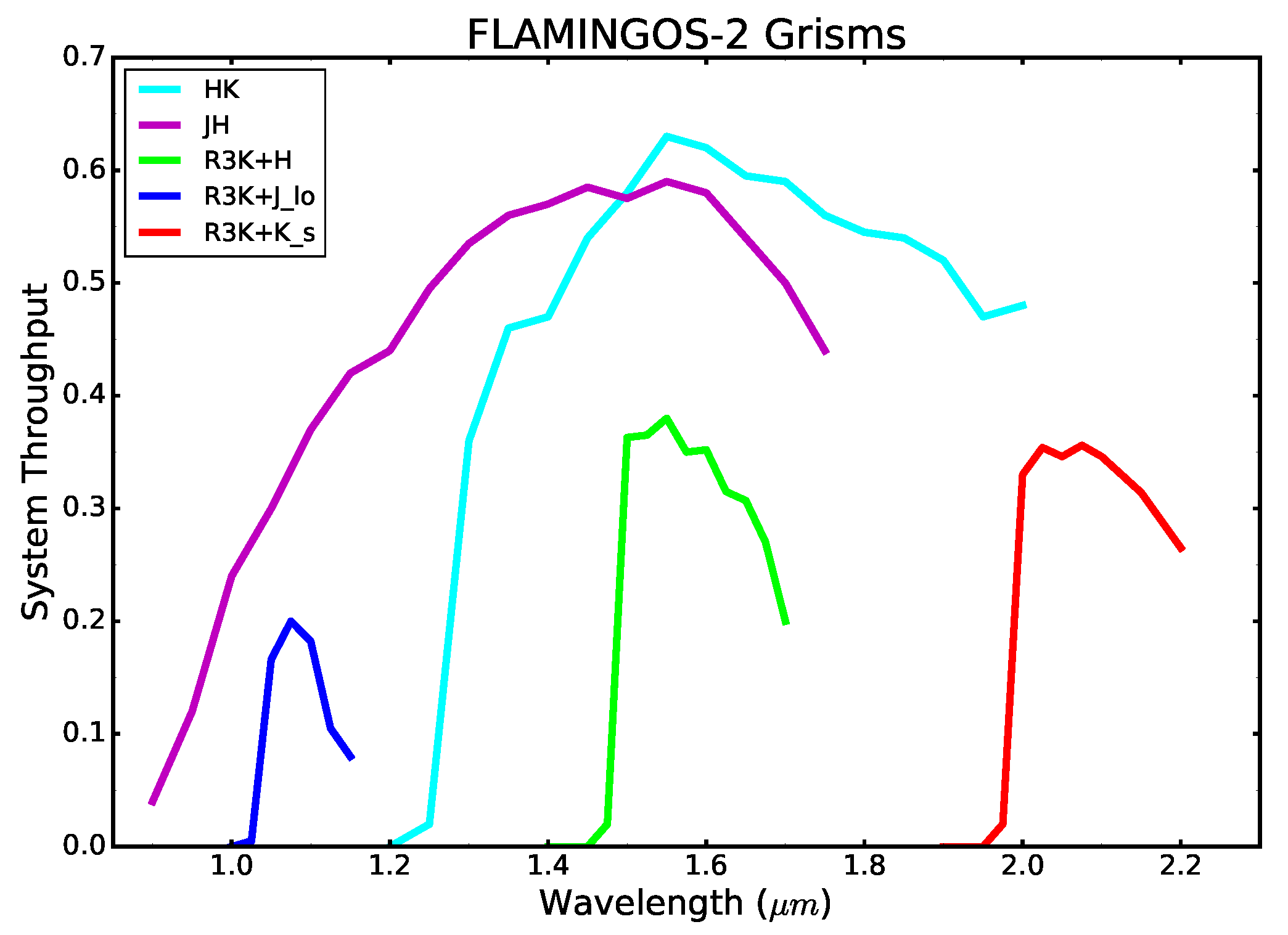
Total system throughput of the F2 grisms. Throughputs include the transmission of the order-sorting filters.